From a 2D floor plan to 3D walls in Blender
A floor plan picture is enough to build a model you can light and render. The trick is to get the scale right first, then draw each wall as a centre line and let a modifier give it thickness. It also keeps every wall easy to move later.
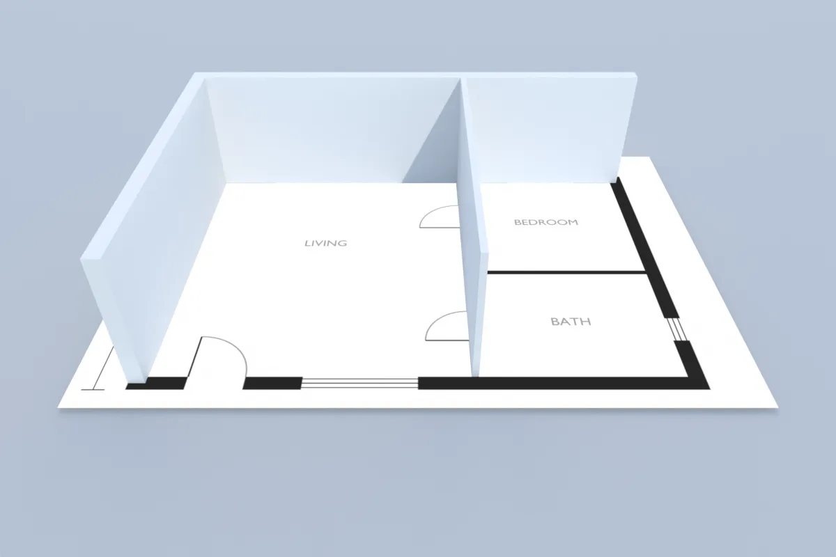
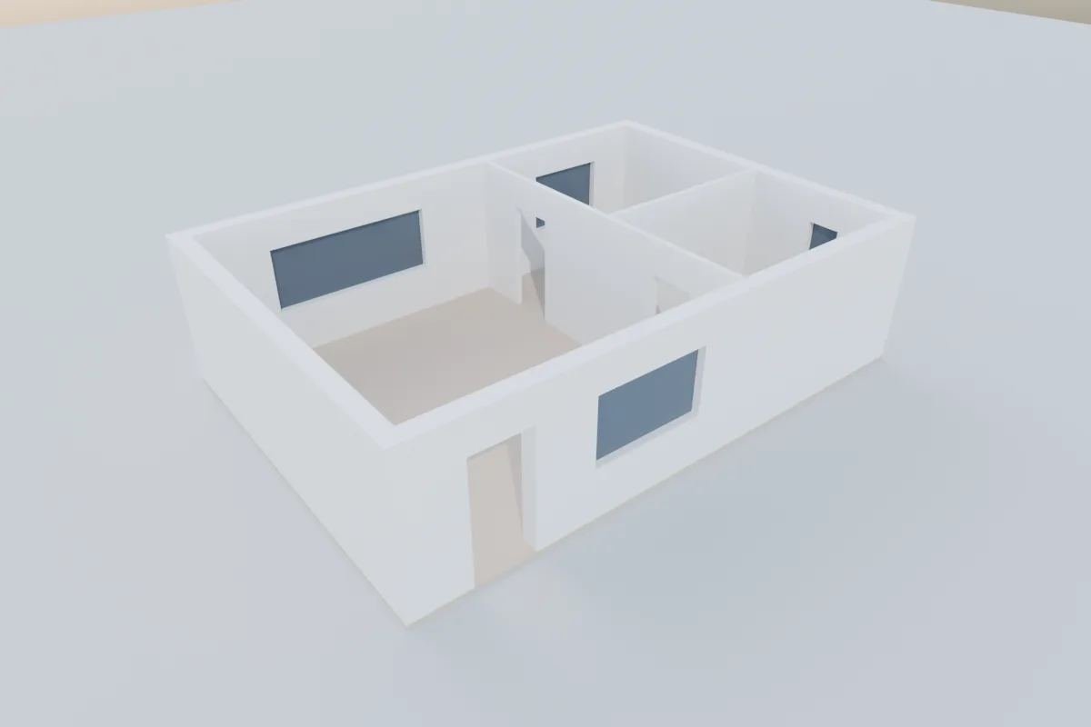
Our own test in Blender 4.5, Cycles. The plan is a 10 × 7 m one-bedroom flat we drew for this guide. The walls are centre lines, extruded 2.7 m and thickened with Solidify (30 cm outside, 12 cm inside). Openings are Boolean cuts.
1. Put the plan in the scene
- Start from an image of the plan: PNG or JPG. If you have a PDF, export the page as an image at 150 to 300 dpi. If you have a DWG or DXF, import the lines instead (see AutoCAD to Blender).
- In the 3D Viewport, choose Add > Image > Mesh Plane (older manuals call it Images as Planes). Before you click Import, set Shader to Shadeless so lights don't change how the plan looks, and Align to +Z so it lies flat.
- The plane comes in 1 m tall by default (Size Mode Absolute, Height 1 m), placed at the 3D cursor. That's wrong for any real plan, which is what the next step fixes.
The other option is Add > Image > Reference, which makes an image empty instead of a mesh. It doesn't render and you can set its Opacity and draw it in Front of the model. Either works for tracing. A mesh plane is easier to scale exactly and stays visible in renders if you want the plan under the model.
2. Set the scale from one known dimension
- Check Scene Properties > Units: Unit System Metric, Unit Scale 1.0, Length Meters. Those are the defaults, and they make 1 Blender unit 1 m.
- Press Numpad 7 for the top view. Pick the longest dimension printed on the plan, here the 10.00 m outside width.
- Use the Measure tool in the toolbar to measure that dimension line on the plane. Say it reads 1.19 m.
- Select the plane, press S and type the ratio: real length divided by measured length, here 10 / 1.19 ≈ 8.4. Press Enter.
- Apply it with Ctrl A > Scale, then measure again. The longer the dimension you measure, the smaller the error.
If the plan has no dimensions, use something with a standard size: an interior door leaf is often around 80 to 90 cm wide, but that varies by country and building, so treat it as a rough check.
3. Draw the walls as centre lines
Drawing each wall's centre line and adding thickness later is quicker than tracing both faces, and it keeps every wall the same thickness.
- Add a new mesh (Add > Mesh > Plane), press Tab for Edit Mode, select all and merge it to one vertex with M > At Center. Move that vertex to a corner of the outside walls, in the middle of the wall's thickness: press N and type its X and Y under Item > Vertex, or press G and type the offsets.
- Press E to extrude the vertex, then X or Y to lock the direction, then type the length from the plan. Typed lengths beat clicking along the image: the plan picture is only as sharp as its pixels.
- Repeat around the outside. To close the loop, select the first and last vertex and press F, which joins them with an edge.
- Draw the interior walls as a separate object, since they'll get a different thickness: back in Object Mode, add another Plane, merge it to one vertex the same way and extrude from there. For a wall that branches off, select the vertex to branch from and press E again. Snapping helps here: turn it on with Shift Tab, set Snap Target to Vertex and Edge, and new points will stick to the outside wall lines.
4. Give the walls height and thickness
- In Edit Mode, select all and press E, Z, then type the wall height, for example 2.7. The lines become thin vertical strips.
- Back in Object Mode, add a Solidify modifier. Set Thickness to the wall thickness (0.3 for the outside walls in our plan) and Offset to 0, which centres the thickness on your line. The default Offset of -1 pushes it all to one side.
- Tick Even Thickness so corners keep the full thickness.
- Do the same on the interior walls object with a thinner value, here 0.12.
End each interior wall line at the inside face of the outer wall, not at its centre line. In our first test the overlapping wall tops showed as small dark specks in the render.
Solidify uses the object's own scale, so apply scale (Ctrl A > Scale) on the wall objects if you scaled them, or the thickness comes out uneven.
5. Cut doors and windows
- Add a cube and size it to the opening: as wide as the window, deeper than the wall, from the sill (often around 0.9 m) to the head (often around 2.1 m). For doors, start it at the floor. Place it by typing values in the N panel: Z location is the sill height plus half the opening's height, for example 0.9 + 1.2 / 2 = 1.5 for a 1.2 m tall window.
- Select the wall, add a Boolean modifier, set it to Difference and pick the cube as the Object.
- Set the cube to display as wire (Object Properties > Viewport Display > Display As > Wire) and hide it from renders. Moving the cube moves the opening.
- Add a thin box with a dark or glass material in each window opening so the holes don't read as empty from outside. For real glass, see window glass in Blender.
Then add a floor under the walls, a ceiling if the camera goes inside, and a camera. Keep the modifiers live until the layout is settled. Applying them early means redrawing the walls when the plan changes.
Add-ons that do some of this
Archimesh is a free extension that adds rooms, doors and windows from parameters, installed from Edit > Preferences > Get Extensions. Its listing says Blender 4.2 and newer and describes it as offered as is, with limited support. Recent reviews ask for fixes on Blender 5. We installed it on 4.5 but built the walls above by hand, so we haven't tested its output. Paid wall tools exist too. For a plan you'll change often, the centre-line method above is easy to edit and needs nothing extra.
What we tested and what we didn't
We built the test model in Blender 4.5 with a script that runs the same operations: the image import with Shadeless and +Z, centre-line walls extruded and thickened with Solidify at Offset 0, and Boolean openings. The interactive steps (Measure, snapping, typed extrudes) follow the manual and weren't recorded separately. We didn't test Blender 5.x or a scanned plan with skewed or blurry lines. If your scan is skewed, straighten it in an image editor first.
Or render it in one click
Once the walls stand, the model can already become a client image. Partilock, the Blender add-on we build (macOS), sends the camera view to an AI image model and returns the image in about a minute. A real 2K render, unretouched:
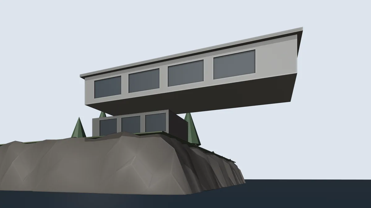
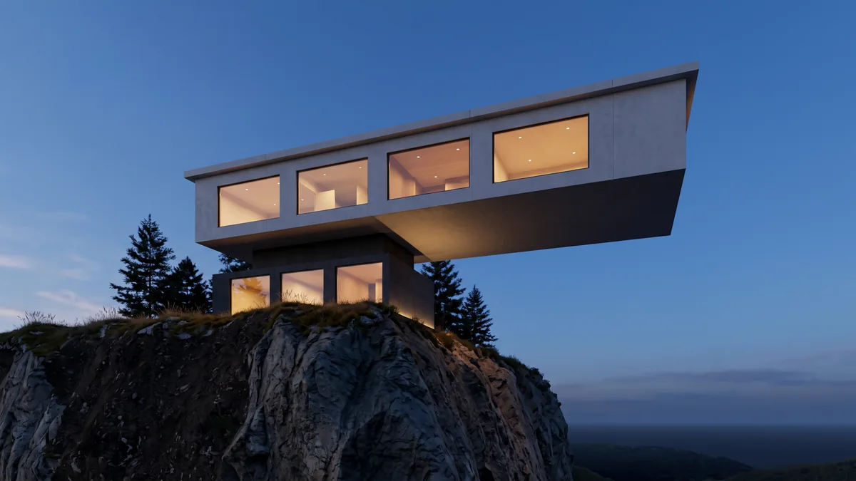
The model was grey boxes with flat dark windows on low-poly rock. The render turned the walls into concrete panels with joints, lit the rooms with downlights and furniture, put trees, grass and rock texture around it and turned the flat dark ground plane into a distant landscape. None of those details are in the model.
It's an image, not geometry, and it can add details that aren't in the model, so check it before a client sees it. 2 free renders to try (1K, watermarked), then 2K from $9 for 18. Install guide, pricing.
Next up, interior lighting in Blender, a wood floor at real scale, or a clean clay render of the new model.